Project Overview
This project develops the architecture of a rocket motor static test pad for measuring motor performance while keeping control and data acquisition centralized in an avionics system. The design combines a load cell for thrust measurement, a thermocouple for exhaust-gas temperature, local data storage, visual and audible safety indicators, remote commands, and a controllable extinguishing mechanism. The mechanical structure was modeled in CAD, while the avionics circuit, embedded logic, interfaces, and PCB were developed and virtually simulated.
The goal was not only to measure a motor. The system was designed so that an operator could start or halt an ignition countdown, stop data acquisition when a test becomes invalid, control the extinguishing mechanism, and retain synchronized sensor data for later performance analysis.
Sense. Decide. Log. Control.
The avionics system turns a static test from a one-time ignition event into a measurable and interruptible experiment.
During a test, the load cell provides the thrust signal $F(t)$ and the thermocouple provides the temperature signal $T(t)$. Samples are time-stamped and stored for later analysis. A compact representation of each data record is
With the reported sampling rate $f_s=50\,\mathrm{Hz}$, consecutive samples are separated by
Standard rocket-performance quantities can then be computed from the recorded thrust profile. For example, total impulse and average thrust are
where $t_b$ is burn time. If propellant mass $m_p$ is known, specific impulse can be expressed as
The Test Sequence Is a State Machine
The control logic separates the experiment into distinct stages: waiting, countdown, ignition, data acquisition, and shutdown. Importantly, the operator can interrupt the sequence instead of being locked into a single irreversible command flow.
The design includes two explicit interruption mechanisms: stop the countdown before ignition and stop data acquisition during a compromised test. The extinguishing mechanism can also be commanded independently when needed.
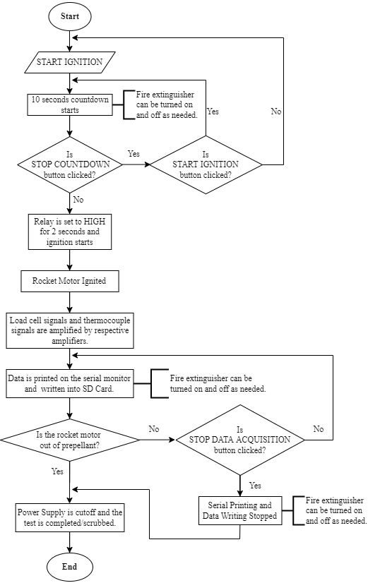
Avionics control flow. The test sequence supports an abortable countdown, ignition, sensor logging, controlled shutdown, and independent extinguisher operation.
Remote Control Without Standing Next to the Motor
The embedded controller accepts the same high-level commands through three interfaces: the serial monitor, a laptop GUI developed in Processing, and a mobile application developed in MIT App Inventor. The interfaces expose the critical actions directly instead of requiring the operator to remember low-level command characters.
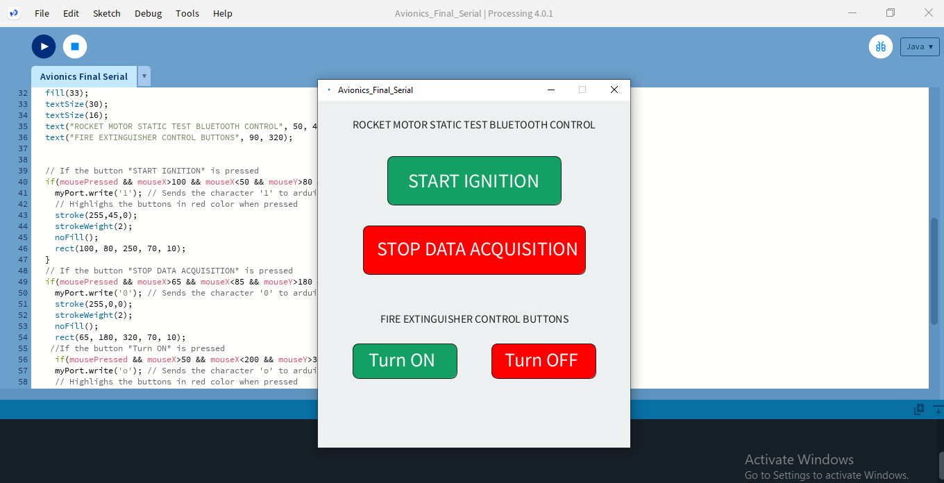
Laptop interface. Start ignition, stop data acquisition, and control the extinguisher from a compact GUI.
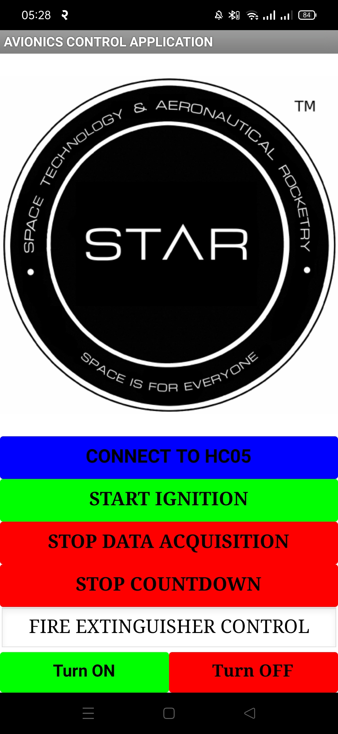
Mobile interface. The same control actions were mapped to a phone application over the planned Bluetooth link.
From Sensors to a Manufacturable Avionics Board
The avionics architecture integrates the microcontroller, thrust sensing, temperature sensing, SD-card logging, relay outputs, status indicators, buzzer, and Bluetooth communication into one system. Individual component circuits were first simulated and then combined into the full circuit before the PCB layout was produced.
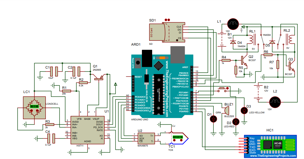
Integrated circuit. The complete simulated avionics architecture.
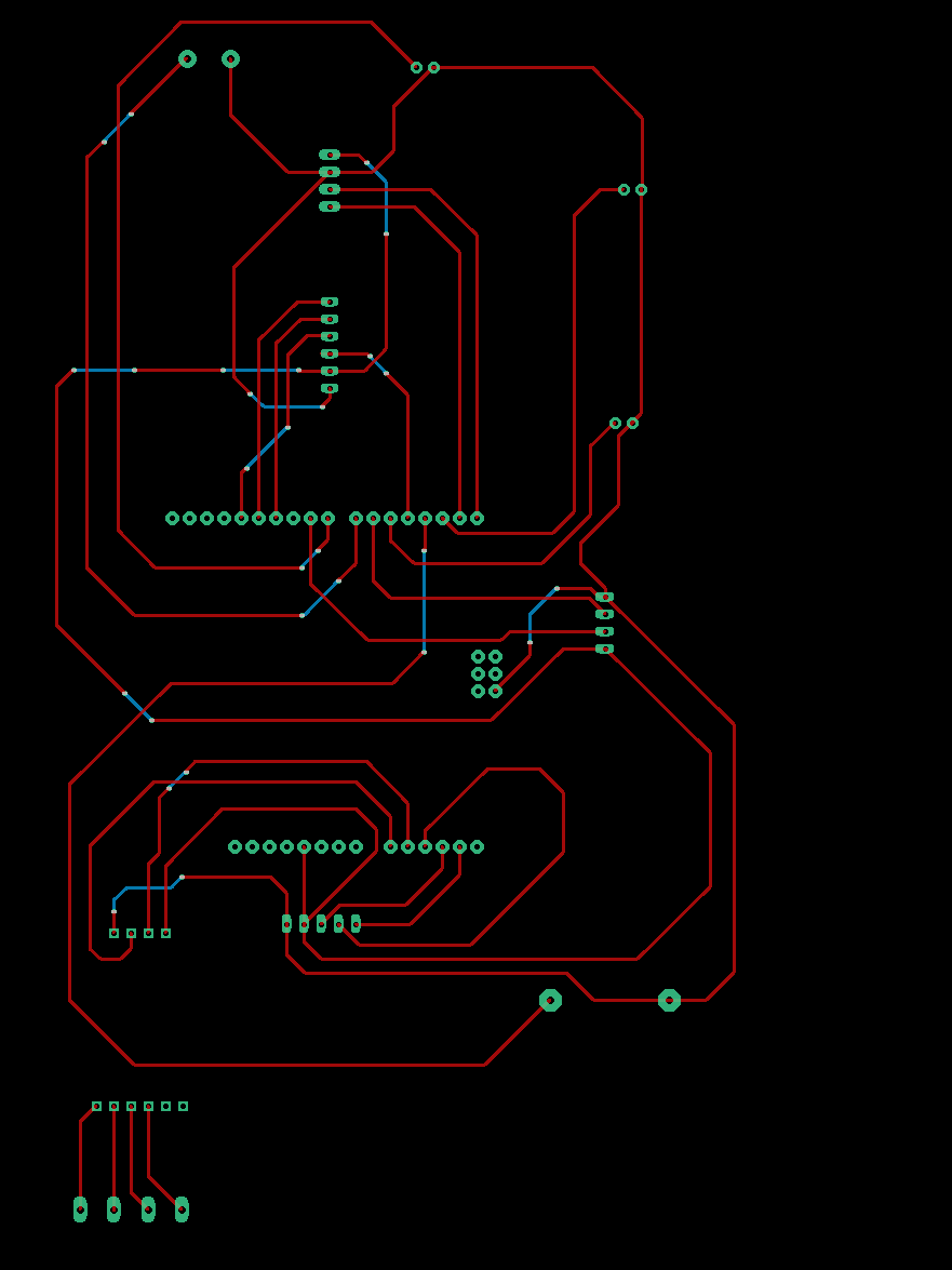
PCB schematic. The component and connection layout prepared before board routing.
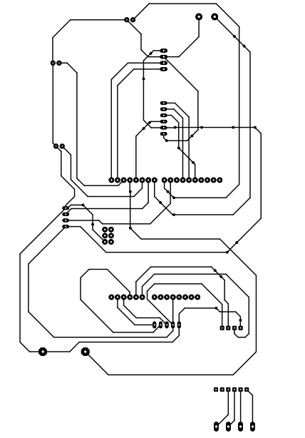
PCB design. The final board layout developed after iterating on practicality and connector placement.
What Worked in Simulation?
The complete circuit and Arduino logic were simulated multiple times. The reported simulation produced the intended 10-second countdown and 2-second ignition command, allowed the extinguishing mechanism to be switched during the simulation, sampled sensor readings at 50 samples per second, and successfully executed the data-acquisition stop logic. The PCB design was also reviewed as complete.
The Bluetooth link itself was not physically tested because an HC05 module was unavailable. The mobile application logic was instead checked independently by modifying the app behavior so the buttons could be exercised without an active Bluetooth connection.
A Complete Test-Pad Architecture
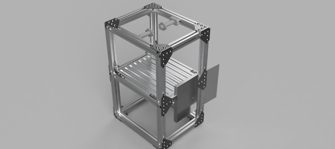
The mechanical concept uses a modular T-slot aluminum structure with a motor mount, ball-transfer support, avionics bay, and gusset-based joints. The project therefore connects three layers that are often treated separately: mechanical support, embedded avionics, and operator interaction.
This project is best viewed as a system-design prototype: a virtually validated architecture for collecting performance data and remotely managing the major phases of a static motor test.